Mechanical design
SolidWorks, AutoCAD, and Inventor development for machines, frames, fixtures, assemblies, formed parts, and production tooling.
Engineering
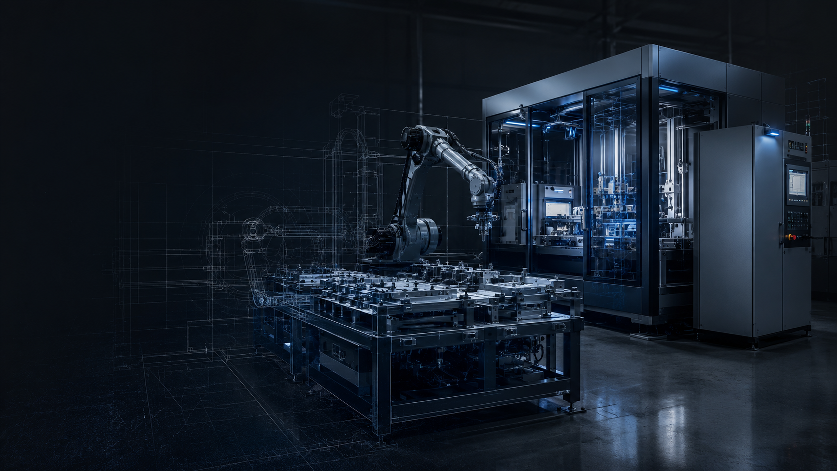
The model is only valuable when the machine, fixture, or assembly can be built, wired, operated, maintained, and trusted in production.
Concept visualization · temporary presentation image
Core disciplines
SolidWorks, AutoCAD, and Inventor development for machines, frames, fixtures, assemblies, formed parts, and production tooling.
Parts and systems developed around cutting, forming, welding, assembly, service access, material use, and real shop capability.
Controlled location, alignment, clamping, access, sequencing, and verification designed into repeatable production setups.
Component layout, machine wiring, labeled conductors, motion devices, sensors, power distribution, and service-minded integration.
Fast concept refinement through CAD, fabrication, fit-up, testing, revision, and documented production learning.
Design intent carried through fabrication and installation instead of stopping at a model or drawing package.
CAD to floor
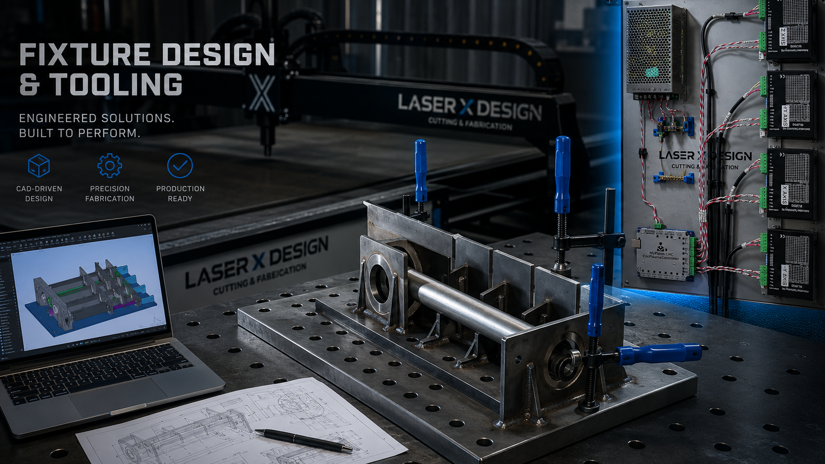
LaserX Design evaluates structure, access, fabrication method, wiring space, assembly sequence, and serviceability while the model is still changing—then carries those decisions through fabrication and integration.
See the X Series case study ↗